Monday, March 11, 2019

An attempt at a 3D printed O Scale Corrugated Grain Silo

Alternate title: What can be done with a 189.99 USD (MSRP) 3D Printer?

Thought I might share this experiment using a 3D printer with a 100 micron resolution and a print volume of a 4.7 inch cube.

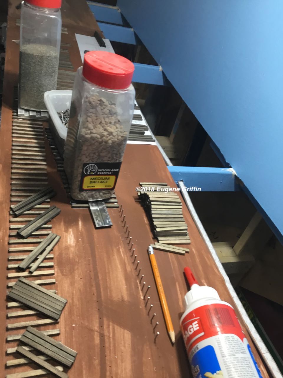
Originally I was going to use my plans to cut styrene sheets (corrugated and smooth) and create the 15 foot diameter by 54 foot tall grain silo in O scale.


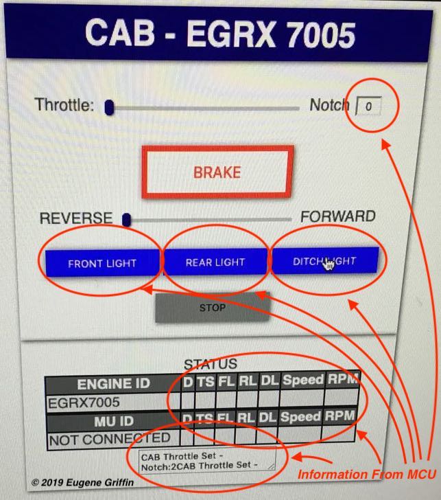
However, after prototyping a throttle, I decide to test the capabilities of the 3D printer.


The Experimental Portion


For the experiment a 15 scale foot diameter by 40 scale inch high portion of the grain silo was created in SketchUp Make.


The corrugated siding has ribs 4 inches on center with heights (depths) of 1 inch. The rivets are 1 inch diameter with a head 1/2 inch in height. The H-beams have a 1 foot dimension (it is an experiment and 1 foot H-beams are a little big).

Two 40 scale inch portions will be stacked for the print.


The STL file is exported from SketchUp Make and imported into Ultimaker Cura. The function of the Ultimaker Cura program is to produce gcode that is used to control this 3D printer.


Prior to printing the above, a section of a larger diameter silo was printed at the layer height of 0.13125 mm (the same as the throttle body).


At this resolution the corrugated ribs have definite striations created by the layering of the PLA. These might be covered by painting or possible use of a heat gun to smooth the PLA. 


The print layer height was increased to 0.0875 mm for the next test print.


The corrugated ribs are definitely smoother, however the H-beams have visible lines. Most of the rivets printed, holes in the the rib in the center of the above photo are missing rivets.

Overall not bad for the first test. 

I miscounted the number of supporting columns on the prototype silo, there should have been 10 not 8.

Back to the drawing board to rebuild the model.

Model Corrected


The printers 100 micron resolution  (0.1 mm) should mean 1/2 inch objects are approaching the minimum size for printing. 

For this printing a 0.0875 mm print layer height was used and the print took 8 hours and 7 minutes. 


This section is 40 scale inches in height and has a 30 scale inch hatch. The 1 inch diameter rivets are visible and are close to the correct scale size. The hatch was printed a little smaller  than expected.


Saturday, March 2, 2019

DIY - ALOC RS-3 Throttle and Locomotive Control (3D Printing and MCUs)

The ESP32 is a microcontroller with both Wi-Fi and Bluetooth onboard for communications. This low power device can be used to design a model locomotive control system. (consideration must be given to available space in the model)


Locomotive Control


The onboard MCU (ESP32) will act as a WEB server as well as a Wi-Fi Access Point for both the throttle and the model locomotive.

After the Wi-Fi connection is established to the MCU. The onboard WEB SEVER will transmit the control page to a web browser. 


The initial design for the engine’s control page is shown above. Key features are a throttle control (slider) that can be notched representing the 8 notches and neutral on the prototype. The throttle can also be reconfigured to be continuous value representing a speed control on traditional model throttles. A slider is also used to control reverse and forward settings.

Lights (FRONT, REAR, DITCH) will be controlled by buttons as shown in the middle of the screen. The BRAKE button will result in speed reduction but will not alter throttle setting. The STOP button will set the throttle to zero and lock the throttle controls.

Feedback

Every control shown on the above engine control page can be set with code residing on that page independent of the WEB server (engine). This makes this page entertaining but not informative.

The objective is to send values to the engine’s MCU, have the MCU control the engine based on those values and then confirm that the engine’s state has changed.

Part one of this feedback loop is accomplished by pressing the control and having code on the page transmit the new value to the engine’s MCU.

Part two is accomplished by the engine’s MCU transmitting the same setting back to the engine control page and having code on that page place the value from the engine’s MCU into the appropriate control. (circled in red on the above photo)

For the throttle notch setting, the feedback loads the current value that the engine’s MCU has sent.The buttons that control the lights will change color from blue as shown to yellow to indicate that the engine has received the “Light ON” command. Additionally, that STATUS area will be updated by values sent from the engine.


The above photos shows the result of pressing the “Front LIght” button. The engine control page sent the command via Wi-Fi to the ESP32 MCU, the MCU activated the LED representing the light and transmitted back the value that changed the button color to yellow


The above photos show the web page generated on an older iPhone by the locomotive's MCU after connecting to the Wi-Fi Access Point 


Throttle


For the throttle an ESP32 will emulate the ALCO RS-3 braking and speed control. The MCU will be programmed with the ability to simulate the release, running, holding, lap, service and emergency functions of braking system as will as the idle through notch 8 of the throttle and the mechanical interlocks between the controls. 


Using a personal 3D printer to build the throttle components allows for more creative deigns.


Tuesday, October 30, 2018

CAD versus Paper

CAD rendition of a 1931 station

Whenever a unique location is found that has rail history, I try to capture as much of the location in CAD.

Each prototype drawing can be easily scaled and the information extracted to produce a model.

Sunday, October 28, 2018

Part 1 - Building a #7 Turnout (Placing and Spiking the Rails)


The NMRA website (https://www.nmra.org) contains a set of recommended practices for building turnouts. Specifically RP-12,  RP-12.x and TN-12 (There is also RP-13.5,6,7,8).  

For quick reference RP-12 and the appropriate RP-12.x document will be used. (For this build RP-12.5 Proto48)


After spiking the straight stock rail, the position of the frog point (red circle in the above photo) is measured from the turnout points and marked. 


The distances for three locations along the curved closure rail are listed in the RP-12.5 document. 

Each location is determined by measuring from the turnout points along the straight stock rail and then from the center of the straight stock rail's railhead over to where the center of the curved closure rail's railhead will be located. (See above circled in red)

Spiking of the rails can begin after the positions are marked and electrical feeder wires are soldered to the frog and rails.


(It is not necessary, but I usually spike the rail leading into the turnout's frog first.)

Once the frog is positioned and the track gauge verified along the frog's rails, the frog is secured with spikes.


After the frog is secured, the curved closure rail is spiked using the marked locations to guide the position of the rail.

The remaining two rails (the straight closure rail and the curved stock rail) are spiked into position based on the track gauge from the corresponding spiked rail.


Tuesday, October 23, 2018

Spiking The Rails


Tools used for spiking Rail:

A- Spiking Pliers
B- Three Point Track gauge
C- Track gauge
D- Tweezers
E- Cutting plier
F- Rotary Tool Cut off Disk (or saw for cutting rail)
(Soldering Iron and Solder not shown)


Before spiking the rails, the wood ties are stained or painted and then glued to the surface of the  module. Allow enough drying time before adding a layer of ballast. The ballast is secured with diluted white glue (PVA).

The rails and tie plates are painted before spiking.

After the paint and glue has dried the rails can be spiked.

If the spikes used have a slightly larger head that isn't visually appealing,  adjust the spike's head size by removing a portion of the head with the cutting pliers.


In order to achieve an even spacing on the wood ties, the rails are held with the three point track gauges. More than one three point track gauge is helpful especially when spiking rail on a curve.

Electrical feeds can be soldered to the bottom of the rails before spiking. The position of the wire for the electrical feed is marked on the ballast and on the rail while the rail is in place. A hole for the feeder wire is drilled into the module and the wire is soldered to the bottom of the rail at the marked location.

Once the rails are positioned and the tie plates are in place using the tweezers, spiking can begin on one of the rails. Before spiking the second rail, ensure the rail spacing is correct by using the track gauge. 

The rail is in gauge when the protruding tabs (A) of the track gauge fit between the rails without binding and the rail does not slip into notch (B). (As shown by in the Orange Circle)

The rails are gauged correctly in the photo. (Red Arrow in Photo)

Spiking O scale rail is not difficult and the number of bent spikes will reduce with practice and patience.


Sunday, October 21, 2018

The Beginning

The location for this model railroad is a space above my desk and extends for approximately 15 feet in either direction.

For this build I will be using modules consisting of track attached to modules with buildings and scenery. I am hoping this will increase usability in the future if I decided to change the theme of the model railroad.


This module is 12 inches by 96 inches and will contain the three parallel track connected by 
crossovers. 

The height in the location is limited, a quick test will ensure there is enough room to reach the models.


The track will be hand laid and consists of painted code 125 rail resting on painted tie plates and spiked to dyed wood ties.


Self-guarded Frogs (Getting ready to spike the #7 turnout)

Turnout with guard rails to guide the wheels through the frog


Turnouts without guard rails, the frog is self-guarded

Proto48 self-guarded Frog


Self-guarded frogs appear in slower speed industrial areas and yards. The area that is being modeled is an industrial area and the prototype inspiration has self-guarded frogs.

Time to start spiking the turnouts.

Inspiration


I enjoy model railroading as a hobby and wanted to see if I can create a small 1/4" scale switching layout, above my work space, based on the above photos.

This BLOG will document the progress.

O Scale versus Proto48 versus what I am doing

Both O scale (1:48) and Proto48 are 1/4” scale. (1 foot equals a 1/4” on the model)

One difference between the two is the distance between the rails of the model. O scale rails model a 5 foot track gauge (1.25 inches when modelled) whereas Proto48 (P:48) models a 4 foot 8.5 inch track gauge. The standard track gauge of North American railroads that I model is 4’ 8.5”. 
Atlas O Scale Wheels (Larger Flange and Wider Tread)

Proto48 Wheels (Prototypical Flange and Tread)

Prototype


A visible difference, between O scale and Proto48 , is the appearance of the wheels. Proto48 wheels appear more prototypical than the O scale wheels (see above pictures). The finer more prototypical Proto48 wheels require different tolerances for track work especially on turnouts.

This model railroad will definitely use the Proto48 wheels. The appearance is closer to the prototype and I am willing to pay the extra for that appearance.

However, there seems to be an association of finer details on Proto48 models, both track and equipment , that will not be pursued on this model railroad. For this reason I labelled the model as O scale with 4’ 8.5” track gauge.