
The ESP32 is a microcontroller with both Wi-Fi and Bluetooth onboard for communications. This low power device can be used to design a model locomotive control system. (consideration must be given to available space in the model)

Locomotive Control

The onboard MCU (ESP32) will act as a WEB server as well as a Wi-Fi Access Point for both the throttle and the model locomotive.
After the Wi-Fi connection is established to the MCU. The onboard WEB SEVER will transmit the control page to a web browser.
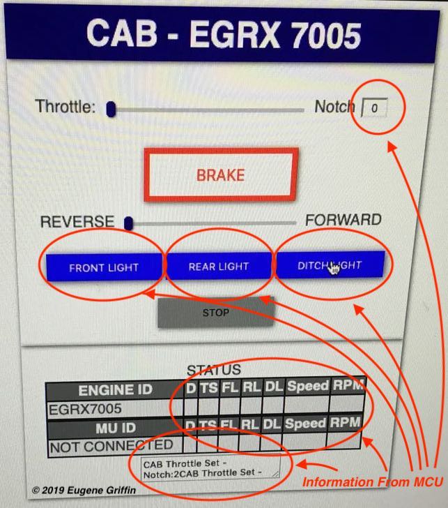
The initial design for the engine’s control page is shown above. Key features are a throttle control (slider) that can be notched representing the 8 notches and neutral on the prototype. The throttle can also be reconfigured to be continuous value representing a speed control on traditional model throttles. A slider is also used to control reverse and forward settings.
Lights (FRONT, REAR, DITCH) will be controlled by buttons as shown in the middle of the screen. The BRAKE button will result in speed reduction but will not alter throttle setting. The STOP button will set the throttle to zero and lock the throttle controls.
Feedback
Every control shown on the above engine control page can be set with code residing on that page independent of the WEB server (engine). This makes this page entertaining but not informative.
The objective is to send values to the engine’s MCU, have the MCU control the engine based on those values and then confirm that the engine’s state has changed.
Part one of this feedback loop is accomplished by pressing the control and having code on the page transmit the new value to the engine’s MCU.
Part two is accomplished by the engine’s MCU transmitting the same setting back to the engine control page and having code on that page place the value from the engine’s MCU into the appropriate control. (circled in red on the above photo)
For the throttle notch setting, the feedback loads the current value that the engine’s MCU has sent.The buttons that control the lights will change color from blue as shown to yellow to indicate that the engine has received the “Light ON” command. Additionally, that STATUS area will be updated by values sent from the engine.


The above photos shows the result of pressing the “Front LIght” button. The engine control page sent the command via Wi-Fi to the ESP32 MCU, the MCU activated the LED representing the light and transmitted back the value that changed the button color to yellow


The above photos show the web page generated on an older iPhone by the locomotive's MCU after connecting to the Wi-Fi Access Point
Throttle

For the throttle an ESP32 will emulate the ALCO RS-3 braking and speed control. The MCU will be programmed with the ability to simulate the release, running, holding, lap, service and emergency functions of braking system as will as the idle through notch 8 of the throttle and the mechanical interlocks between the controls.

Using a personal 3D printer to build the throttle components allows for more creative deigns.
No comments:
Post a Comment
Note: Only a member of this blog may post a comment.